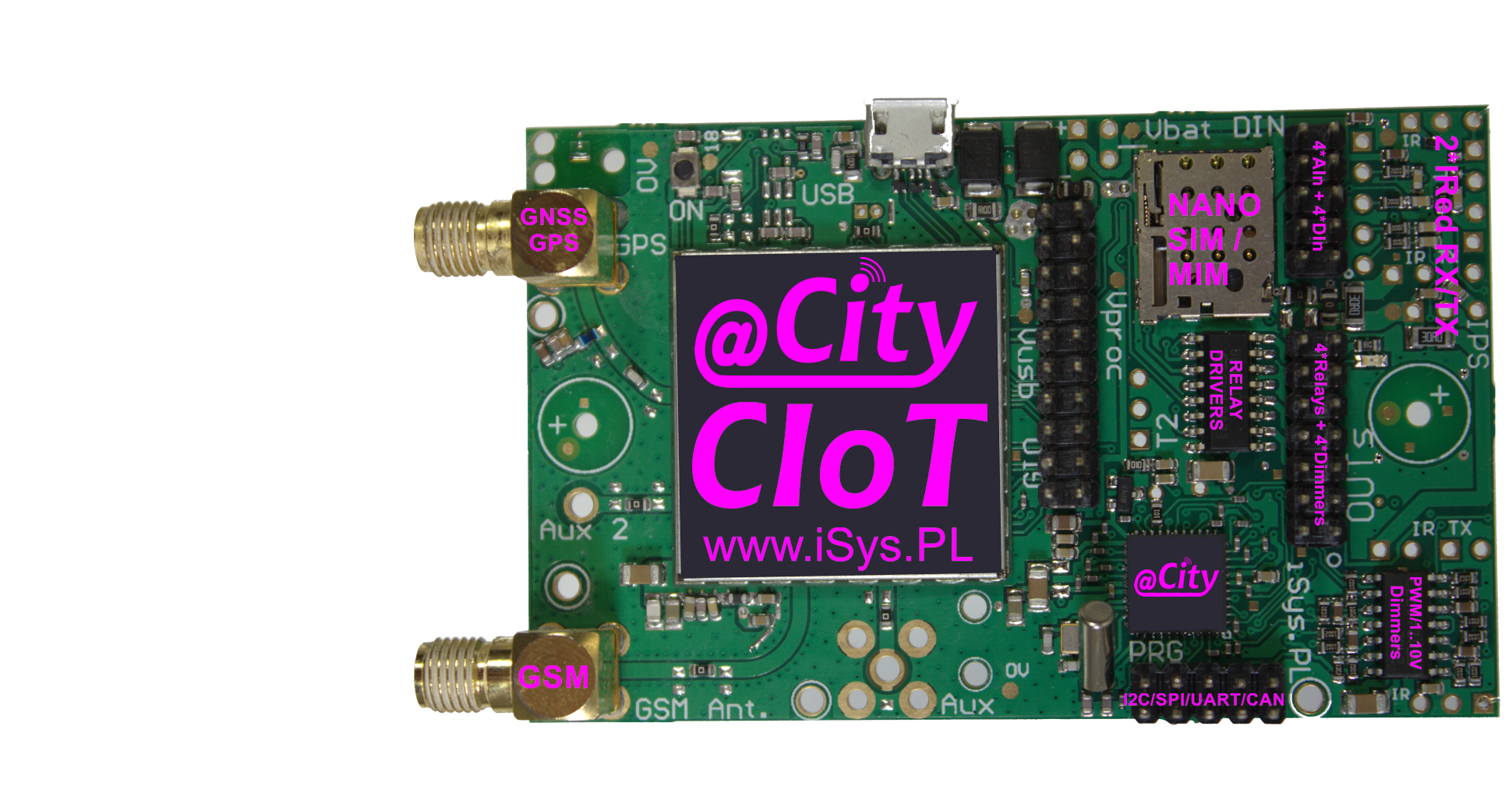
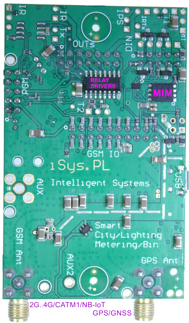
IoT/IIoT GSM (@City IoT GSM)
IoT / IIoT GSM system is an smart solution of the Internet of Things with a GSM interface:
- IoT - Internet of Things
- IIoT - Industry Internet of Things
- BAS - wireless extensions of the Building Automation System variants: eHouse WiFi, Ethernet, PRO
- BMS - wireless extensions of the Building Management System eHouse BMS
- BIM - wireless sensors that are an extension of eHouse BIM (Building Information Modeling)
- wireless extensions "actuators" and sensors
- @City IoT platform/cloud (Software, Web-Applications)
- controllers (IoT nodes) mounted in lamps, devices, machines
- system server eHouse.PRO / @City IoT (microcomputer) integrating all LoRaWAN/GSM controllers and others into a single system eHouse Hybrid/BMS + @City
This allows integration and operation in synergy of any device in eHouse and @City IoT systems for more distributed applications.
It can work under the supervision of the eHouse PRO/BMS/Hybrid, @City server integrating other wired and wireless communication interfaces available in the eHouse and @City IoT systems.
The following systems are available: eHouse RF, eHouse WiFi, IoT/IIoT LoRaWAN, IoT/IIoT GSM 2G..4G/CATM1/NBIoT or wired eHouse CAN, eHouse RS485/422, eHouse Ethernet, eHouse PRO.
Creating a hybrid system allows any choice of communication interfaces, if it is conditioned by technical requirements, preferences or the budget of the project.
The IIoT/IoT GSM system has a very rich functionality and great customization and configuration options:
- Main communication interface GSM, 2G..4G (CATM1, NBIoT)
- Optional control from a smartphone WWW
- Work under the supervision of the server eHouse PRO/BMS, @City IoT - microcomputer
- Built-in GPS/GNSS receiver
- Possibility to update the software and upload dedicated software for the application and partner
- ADC analog measurement inputs
- CAN serial interface
- Possibility of full customization for the needs of the application or partner
- Serial interface UART, RS-232TTL, RS-485
- Optional MEMS sensors module
- Binary inputs (0..4) (programmable) - connection of sensors, control switches
- Infrared output - for remote control of external devices/controllers (A/V, HiFi, RTV, Air-conditioning, HVAC, short range communication between devices)
- Binary outputs (0..4) with relay drivers - for switching on lighting or other devices
- Infrared input - for remote control of all functions of the current controller/device/lamp
- Optional MEMS, SIoT sensors on the external sensor module:
- electricity consumption
- resistance
- light level
- gas concentrations
- 3-axis vibration and acceleration
- proximity (10cm)
- ground moisture
- proximity (4m) - Time of Flight
- capacity
- 3-axis gyroscope
- 3-axis accelerometer
- temperature
- air pollution
- humidity
- 3-axis magnetometer
- color (R, G, B, IR)
- 3-axis inclinometer
- solid particles 1, 2.5, 4, 10um
- ALS (ambient light)
- lightning up to 40km
- pressure
- 0..4 - PWM-DC or 1..10V outputs for dimming LED lamps or power supplies:
- Regulation of the current of infrared diodes - additional heating of the workplace and maintaining individual thermal comfort at the desk
- RGBW Color Control (3 or 4 channels) - Ambient, Decorative, Alarm, Evacuation Lights
- White Balance (Temperature) Control 2 channels (for warm and cold white)
- Direct power supply to high-power diodes
- Speed ‚Äč‚Äčcontrol of motors or fans
- Current regulation of special (COB, PowerLed, IR, UVA + UVB + UVC, laser) and high power diodes
Additional sensors of the eCity IoT GSM controller with GSM + GPS communication
- lighting sensor with GSM + GPS
- static particles 1, 2.5, 4, 10um sensor with GSM + GPS
- humidity sensor with GSM + GPS
- vibration and acceleration sensor with GSM + GPS
- 3-axis magnetometer sensor with GSM + GPS
- current/voltage sensor with GSM + GPS
- 3-axis inclinometer sensor with GSM + GPS
- ALS lighting sensor with GSM
- proximity (4m) sensor - Time of Flight with GSM + GPS
- capacity sensor with GSM + GPS
- color R, G, B, IR sensor with GSM + GPS
- temperature sensor with GSM + GPS
- power consumption sensor with GSM + GPS
- 3-axis accelerometer sensor with GSM + GPS
- resistance sensor with GSM + GPS
- lightning/storm up to 40km sensor with GSM + GPS
- 3-axis gyroscope sensor with GSM + GPS
- air pollution sensor with GSM + GPS
- light level sensor with GSM + GPS
- earth moisture sensor with GSM + GPS
- pressure sensor with GSM + GPS
- proximity (10cm) sensor with GSM + GPS
- gas concentration sensor with GSM + GPS
Common Interfaces GSM+GPS converter/gateway
- UART<=>GSM + GPS converter/gateway
- infrared<=>GSM + GPS converter/gateway
- NFC<=>GSM + GPS converter/gateway
- RS-232<=>GSM + GPS converter/gateway
- RS-485<=>GSM + GPS converter/gateway
- RS-422<=>GSM + GPS converter/gateway
- CAN<=>GSM + GPS converter/gateway
- BACNet<=>GSM + GPS converter/gateway
- Modbus RTU<=>GSM + GPS converter/gateway
- DMX<=>GSM + GPS converter/gateway
- Dali<=>GSM + GPS converter/gateway
Additional functions of @City IoT, eHouse Server Software
- BIM - Building Information Modeling. Collecting information and processing it
- Archiving data, creating reports, saving in databases
- Creating dedicated algorithms to change or extend the functionality of the system
- Control via WWW (html-link), SMS
- BACNet IP, ModBus TCP, MQTT, UDP, TCP, UDP + TCP integrations, file system, database
- local work and/or via eHouse or @City IoT cloud
- remote work direct communication (permanent public IP address) or indirect via eHouse Proxy Server
Initial System Configuration and Initialization
Although this information are for eCity GSM controllers, about 90% of settings are the same for eCity LoRaWAN, eHouse WiFi, eHouse CAN/RF for standarization
- Cloud and local version
- remote initial system configuration (cloud)
- Selection of CSS styles for displaying individual screens (themes)
- Default Controler (IoT Node) configurations
- Default names of controllers, outputs, inputs, dimmers, sensors
- Individual driver configurations - (modified configuration from default)
- Individual controllers names: outputs, inputs, dimmers, sensors
- Add/remove default controller scopes
- Adding/Removing individual controllers (modified configuration from default)
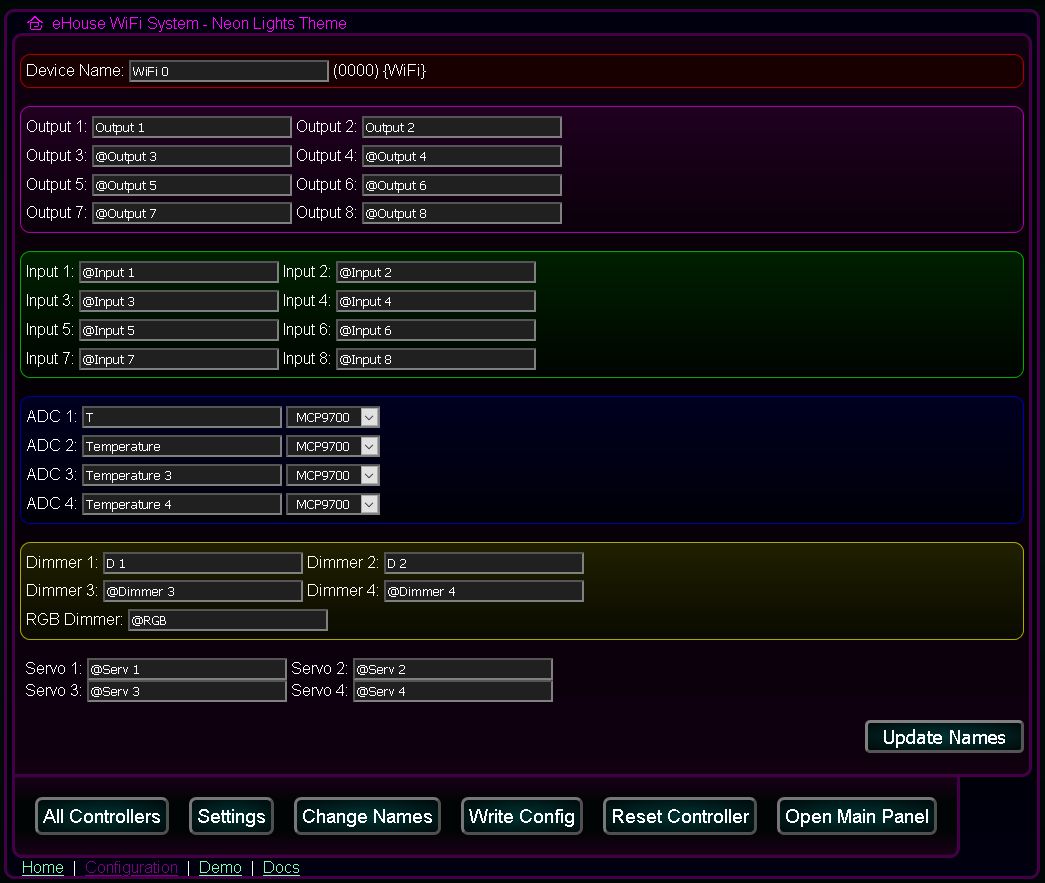
Edit Names
Signals starting with @ are not displayed on the panel. Similarly, unchanged names (output.., input, dimmer..). These names are displayed in the controls for visualization and remote control of the system.
- Individual controller name or prefix for default names
- Names of individual binary outputs (on/off)
- Names of binary inputs (on/off)
- Names of measurement inputs (ADC) and type of the sensor
- Names of single and RGB dimmers
- Drive/Servo names (dual outputs)
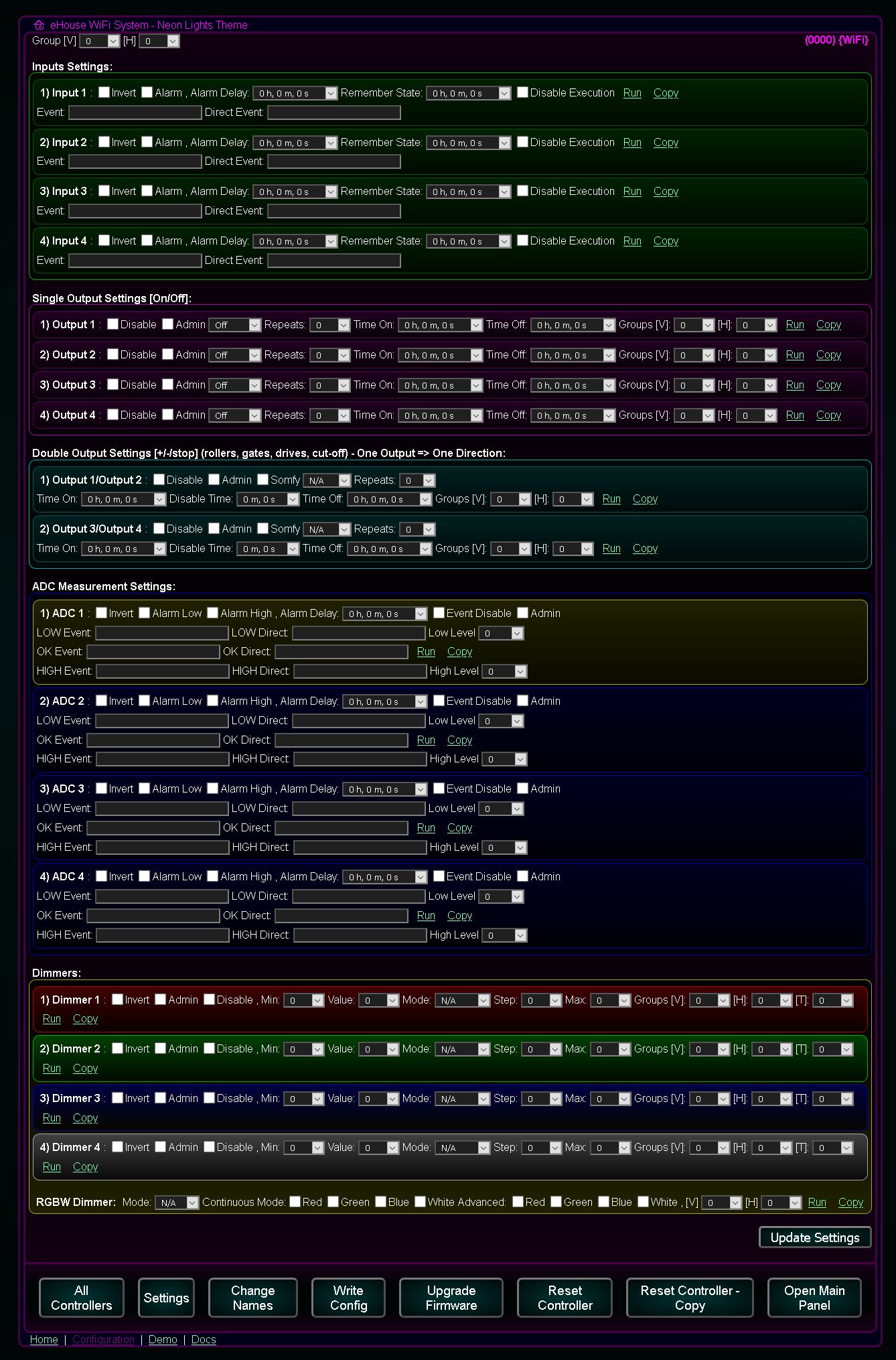
Advanced configuration of controllers
It allows you to pre-configure templates for all new controllers as well as individual configuration of drivers (different from the template).
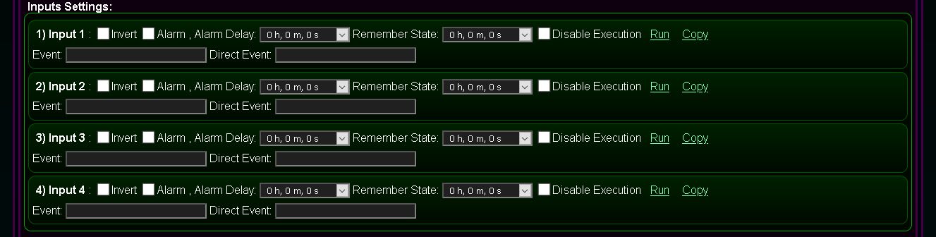
Initial configuration of the controller binary inputs - default or individual
- Invert - (input inverted mode 0->1)
- Alarm - (activation of the alarm function)
- Alarm Delay - (alarm activation delay - if the signal disappears before this time, it will not be activated)
- Remember State - (time to remember triggering the input)
- Event - (description of the event/command)
- Direct Event - (command/event code in hexadecimal format copied from the event/command editor *)
- Disable Execution - (blocking the execution of the command associated with the activation of the input)
- Run - Run the configuration command - save to the queue (cloud configuration)
- Copy - Generating the event code for the configuration of a given input to be copied via the clipboard.
It will be run automatically each time the controller is reset.
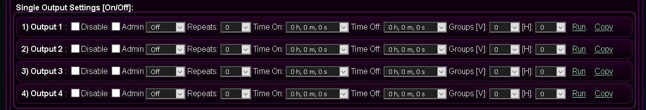
Initial configuration of the controller binary outputs (on/off) - default or individual
The content of this panel has several functions:
- creating advanced events/configuration control commands - writing to the queue (Run)
- creating advanced events/configuration control commands to be copied via the clipboard (Copy)
- initial controller configuration (after each reset). The current state of all fields is saved on the system server after pressing the common button Update Settings
- Disable - Disable output status change. Ignoring control commands for a single output (e.g. when used as a dual output to control actuators / valves)
- Admin - Allows you to change some options such as Disable)
- Repeats - Number of repetitions of switching on the output (cyclic mode)
- Time On - Time to turn the output on (for On/Toggle command). After this time, the output will be turned off.
- Time Off - Time off the output. This parameter is important if the number of repetitions Repeats is greater than zero
Group V - Vertical grouping for multiple device control (eHouse WiFi controller only)Group H - Horizontal grouping for multiple device control (eHouse WiFi controller only)- Run - Run a configuration or output control command - save to a queue (configuration/run in the cloud)
- Copy - Generating an event code to configure or control the output data to be copied via the clipboard.
It will be run automatically each time the driver is reset.
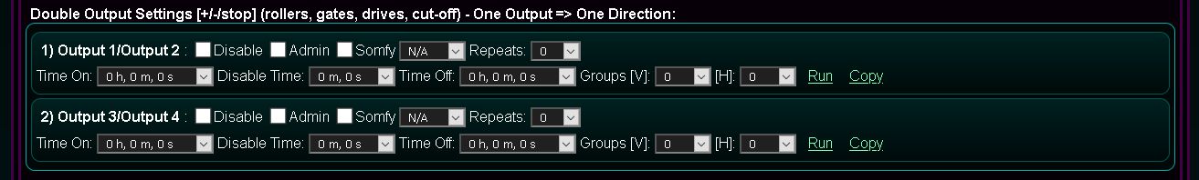
Initial configuration of double outputs (open/stop/close) of the controller {drives control} - default or individual
- creating advanced events / configuration control commands - writing to the queue (Run)
- creating advanced events / configuration control commands to be copied via the clipboard (Copy)
- initial driver configuration (after each reset). The current state of all fields is saved on the system server after pressing the common button "Update Settings"
- Disable - Output pair change lock. Ignoring control commands for dual outputs (e.g. when used as a single output to control on/off devices)
- Admin - Allows you to change some options, such as Disable, Somfy)
- Somfy - drive control mode with Somfy controller (1st line - open, 2nd line - close, both lines - stop). Selecting this mode for a normal drive may damage the drive due to the simultaneous activation of both directions for the stop function
- Repeats - Number of repetitions of switching on outputs (cyclic mode)
- Time On - The time when the outputs are turned on (for the Open/Close command). After this time, the output will be turned off.
- Time Off - Time for turning off of outputs. This parameter is important if the number of repetitions Repeats is greater than zero
Group V - Vertical grouping for multiple device control (eHouse WiFi controller only)Group H - Horizontal grouping for multiple device control (eHouse WiFi controller only)- Run - Run a configuration or output control command - save to a queue (configuration/run in the cloud)
- Copy - Generating an event code to configure or control the output data to be copied via the clipboard.
It will be run automatically each time the driver is reset.
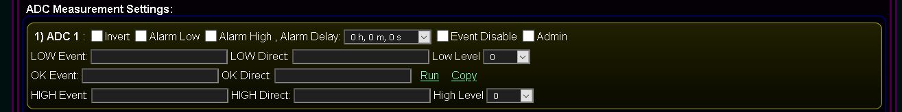
Initial configuration of measuring inputs (ADC) of the controller - default or individual
- Invert - inverted input mode (100% -x)
- Alarm Low - (activation of the alarm function when the value falls below the programmed lower threshold)
- Alarm High - (activation of the alarm function when the value falls above the programmed upper threshold)
- Alarm Delay - (alarm activation delay - if the value returns to the range between (min, max) before this time - it will not be activated)
- Low Event - (description of the event/command)
- Low Direct - (command / event code in hexadecimal format copied from the event editor *) to decrease the measured value below the programmed lower threshold
- Low Level - Minimum level (lower)
- OK Event - (description of the event / command)
- OK Direct - (command / event code in hexadecimal format copied from the event editor *) for the measured value in the range (min, max) - only when changing one of the thresholds (min or max)
- High Event - (description of the event / command)
- High Direct - (command / event code in hexadecimal format copied from the event editor *) executed when the measured value increases above the programmed upper threshold
- High Level - Maximum level (upper)
- Event Disable - (blocking the execution of commands related to the input)
- Admin - Allows you to change some options, such as Invert
- Run - Run the configuration command - save to the queue (cloud configuration)
- Copy - Generating the event code for the configuration of a given input to be copied via the clipboard.
It will be run automatically each time the driver is reset.
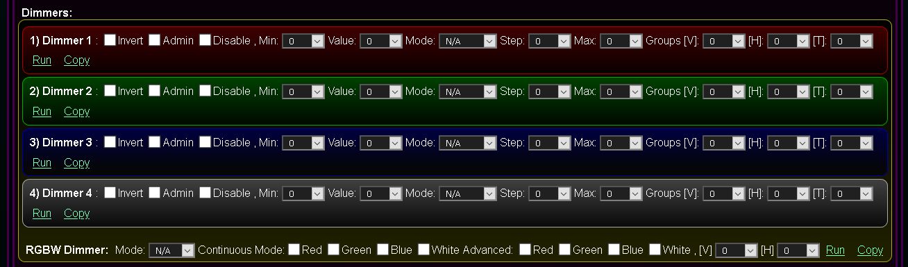
Initial configuration of adjustable outputs PWM/1..10V (0..100%) of the controller {dimming lighting or LED power supplies} - default or individual
- creating advanced events/configuration control commands - writing to the queue (Run)
- creation of advanced events/configuration control commands to be copied via the clipboard (Copy)
- initial controller configuration (after each reset). The current state of all fields is saved on the system server after pressing the common button Update Settings
- Disable - Disable dimmer output. Ignoring control commands for dimmers (e.g. when used as a binary output)
- Admin - Allows you to change some options, such as Disable , Min , Max )
- Min - minimum value (0..100%) or (0..255). The signal value is always greater than or equal to this value
- Value - target value (0..100%) or (0..255). The signal value tends to this value
- Mode - dimmer operating mode
- N/A - no change
- Stop - stop the dimmer in the current state
- + - increase of the lighting value to the value Max (unless the dimmer is stopped)
- - - decrease of the lighting value to the value Min (unless the dimmer is stopped)
- Set - immediate dimmer level setting
- Toggle - stop (if the dimmer is in motion) or change the value in the opposite direction (if the dimmer is in the steady state)
- -Value - one-time reduction of the dimmer's value by the step value
- +Value - one-time increase of the dimmer's value by the step value
- Params - setting additional dimmer parameters
- Modify - dimmer modification
- Inc - increase of the lighting value to Max (unless the dimmer is stopped) + advanced functions
- Dec - decrease of the lighting value to the value Min (unless the dimmer is stopped) + advanced functions
- Stop - stopping the dimmer in the current position
- Change - dimmer value change
- Step - Change step value
- Max - minimum value (0..100%) or (0..255). The signal value is always less than or equal to this value
Group V - Vertical grouping for multiple device control (eHouse WiFi controller only)Group H - Horizontal grouping for multiple device control (eHouse WiFi controller only)- Run - Run a configuration or output control command - save to a queue (configuration / run in the cloud)
- Copy - Generating an event code to configure or control the output data to be copied via the clipboard.
It will be run automatically each time the driver is reset.
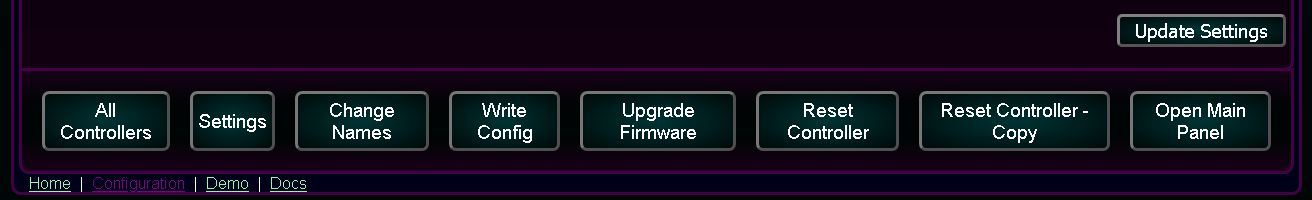
Full configuration in the form is saved on the server (local or cloud) after pressing the Update Settings button.
In the case of cloud configuration, it is automatically copied to the local server after the local server is reset.
In case of local configuration, it is started after pressing the Write Config button.
The driver software update is performed after clicking the Firmware Update button.
Full Screen Configuration of an individual controller or general template
IoT LoRaWAN / GSM controller documentation
@Light, @City, IoT/IIoT GSM + GPS - Options
eCity IoT/IIoT Platform for eCity LoRaWAN/GSM devices